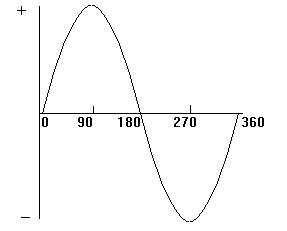
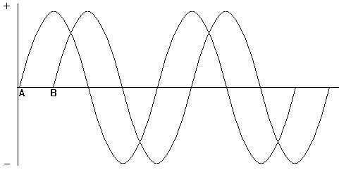
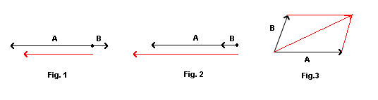
| The generator at the power station which produces our AC mains rotates through 360 degrees to produce one cycle of the sine wave form which makes up the supply. In the next diagram there are two sine waves. They are out of phase because they do not start from zero at the same time. To be in phase they must start at the same time. The waveform A starts before B and is LEADING by 90 degrees. Waveform B is LAGGING A by 90 degrees. The next left hand diagram, known as a PHASOR DIAGRAM, shows this in another way.The phasors are rotating anticlockwise as indicated by the arrowed circle. A is leading B by 90 degrees. The length of the phasors is determined by the amplitude of the voltages A and B. Since the voltages are of the same value then their phasors are of the same length. If voltage A was half the voltage of B then its phasor would be half the length of B. All this has nothing to do with "set your phasors on stun". 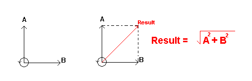 \ \The result of the two voltages can be found by completing the phasor diagram as shown on the right. The resulting voltage is slightly greater in amplitude than A or B, and leads B by 45 degrees and lags A by 45 degrees. Since the two voltages are 90 degrees apart, then the resultant can be found by using Pythagoras, as shown.
Capacitance in AC Circuits Tutorial |
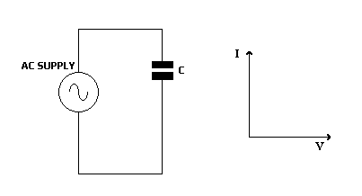
| Here the ac current through the circuit leads the voltage by 90 degrees. Ohm's Law cannot be applied because current and voltage are not both at maximum at the same time. You need to find the capacitive reactance to be able to use Ohm's Law. |
|
In Fig. 1 above, the two phasors are 180 degrees out of phase. The resultant voltage is found by subtracting B from A. The result is a voltage in phase with A but slightly smaller in amplitude.In Fig. 2 the two voltages are in phase and are added to find the result, which is in phase with A and slightly greater in amplitude. In Fig.3 a parallelogram must be constructed to find the resulting voltage. |