A number of motors of comparatively small ratings are manufactured for operation on single phase ac supply. Most of them, built in fractional horse power sizes, are technically termed as “small motors, a small motor being defined as ‘a motor built in a frame smaller than having a continuous rating of 1hp” An induction of the number of such motors can be had from the fact that the sum of total of all fractional-horse power motors in use to-day far exceeds the total of integral horse power motors of all types. Single phase motors perform a great variety of useful services in the home, the office, the factory, in business establishment, on the farm and many other numerous applications where electricity is available. These find interesting applications in automatic control devices of various types. Since the requirements of the numerous applications differ so widely, the motor-manufacturing industry has developed several types of such motors, each type having operating characteristics that meet define demands.
Single phase ac motors may be divided into three general classes namely
(i) Induction Motors
(ii) Commutator Motors
(iii) Synchronous Motors.
Email Based Homework Assignment Help in SINGLE PHASE AC MOTORS
Crazy Engineer is the best place to get answers to all your doubts regarding explanation of alternators including its construction and working principle with diagram and examples. You can submit your school, college or university level homework or assignment to us and we will make sure that you get the answers you need which are timely and also cost effective. Our tutors are available round the clock to help you out in any way with electrical engineering.

POLYPHASE INDUCTION MOTOR
The polyphase induction motor is the most widely used ac motor due to its low cost, simple and extremely rugged construction, high reliability, high efficiency, reasonably good power factor, low maintenance cost and simple starting arrangement.
It differs from other types of electric motors in that there is no electrical connection from the rotor winding to any source of supply. The necessary current and voltage in the rotor circuit are produced by induction from the stator winding. This is the reason that it is called the induction motor.
CONSTRUCTION
The induction motor essentially consists of two parts
(i) Stationary part known as stator and
(ii) The revolving part, known as the rotor.
1. Stator. Stator of a 3-phase induction motor is similar in construction to that of a 3-phase synchronous machine. The stator winding, also sometimes known as primary winding, is placed in slots on the inner periphery of the core. The core and windings are enclosed in cast iron frame. The stator winding is usually arranged for 3-phase power supply, the phases of which may be connected either in delta or star as per design of the machine. It is would for a definite number of poles as per requirement of speed-greater the number of poles lesser the speed and vice-versa for a supply of given frequency.
2. Rotor. The rotors employed in 3 phase induction motors are of three types namely
(a) squirrel cage
(b) Wound rotor
(c) Double Cage.
(a) Squirrel Cage Rotor. Almost 90 percent of induction motors are provided with squirrel cage rotor because of its very simple, robust and almost instrucible construction. Squirrel cage rotor is constructed of a laminated core with the conductors 9copper or aluminum bars) placed parallel, or approximately parallel to the shaft and embedded in the core surface. At each end of the rotor, the rotor conductors are all short-circuited by continuous end rings of similar materials to that of conductors. The slots on the rotor are usually skewed in order to obtain a more uniform torque and reduce the magnetic humming noise while running and reduce the locking tendency of the rotor.
(b) Wound Rotor. Such a rotor is wound with an insulated winding similar to that of stator winding and for the same number of poles as that of the stator. The rotor winding is always three phase winding even when the stator is wound for two phases.
(c) Double Squirrel Cage Rotor. Such a rotor carries two squirrel cage windings embedded in two rows of slots. The outer slots contain a high resistance and low leakage reactance winding and the inner slots contain a low resistance and high leakage reactance winding. The outer winding bars are usually of manganese brass while the inner winding bars are of red copper.
Email Based Homework Assignment Help in POLYPHASE INDUCTION MOTORS
Crazy Engineer is the best place to get answers to all your doubts regarding explanation of alternators including its construction and working principle with diagram and examples. You can submit your school, college or university level homework or assignment to us and we will make sure that you get the answers you need which are timely and also cost effective. Our tutors are available round the clock to help you out in any way with electrical engineering.
ALTERNATORS
 |
| Revolving Field Salient Pole Type Alternator |
Construction and Working Principle
The electrical machine, which generates ac, is known as ac generator or alternator. Similar to dc generator it operates on the fundamental principle of electro-magnetic induction. It essentially consists of two parts namely the armature and field magnet system. The alternator may be constructed with either the armature or the field structure as revolving member. Small ac generators and of low voltage rating are commonly made with rotating armature. In such generators the required magnetic field is produced by dc electro-magnets placed on the stationary member, called the stator, and the current generated is collected by means of brushes and slip-rings on the revolving member, called the rotor.
Practically all large rating generators are made with revolving field. In such generators revolving field structure or rotor has slip-rings and brushes for supply of excitation current from an outside dc source and the stationary armature, (also called the stator), which is made up of thin silicon steel laminations securely clamped and held in place in the steel frame, accommodates coils or winding in the slots. The slots provided on the stator core are mainly of two types viz open type or semi-closed type slots. Totally closed type slots are never used.
The field system is just like that of a dc generator which is excited from a separate source of 125 or 250 V dc supply. The excitation is usually provided form a small dc shunt or compound generator, called the exciter, mounted on the shaft of the alternator itself.
The stationary armature and revolving field system have some inherent advantages such as (i) light revolving system (ii) easier to insulate the high voltage winding when mounted on stationary structure (iii) connection of load circuit without passing through slip-rings for 125 V or 250 V 9v) cooling of armature winding is more readily possible. Rotors are of two types viz salient-pole type and non-salient or smooth cylindrical types.
Salient pole type rotor is used almost entirely for slow and moderate speed alternators (hydro generators), since it is least expensive and provides ample space for the field ampere-turns. Salient poles cannot be employed in high speed generators, such as turbo-generators, on account of very high peripheral speed (100 to 170 m/s) and the difficulty of obtaining sufficient mechanical strength. Such rotors have large diameter and small axial length.Smooth cylindrical or non-salient pole type rotors are used in very high speed alternators, such as turbo-generators. Such rotors have two or four poles and small diameter and long axial length. These are better in dynamic balancing and quieter in operation. Windage losses are also less.
EMF Equation. The emf equation for an alternator is given as
Erms per phase = 4.44 Kd Kp Ø f T volts
Where Kp is coil span factor or pitch factor and is equal to cos α/2 where α is angle by which coil span falls short and is equal to unity for full pitch winding, Kd is the distribution or breadths factor and is equal to (sin mβ/2 / msin β/2) ; m being the number of slots per pole per phase and β = 1800/ number of slots per pole , is the useful flux per pole in webers, f is the frequency in hertz and T is the number of turns per phase.
Rating of Alternators. The alternators are rated in KVA or MVA.
Email Based Homework Assignment Help in Alternators
Crazy Engineer is the best place to get answers to all your doubts regarding explanation of alternators including its construction and working principle with diagram and examples. You can submit your school, college or university level homework or assignment to us and we will make sure that you get the answers you need which are timely and also cost effective. Our tutors are available round the clock to help you out in any way with electrical engineering.
How Analog-to-Digital Converter (ADC) Works
Introduction
Signals in the real world are analog: light, sound, you name it. So, real-world signals must be converted into digital, using a circuit called ADC (Analog-to-Digital Converter), before they can be manipulated by digital equipment. In this tutorial we will give an in-depth explanation about analog-to-digital conversion yet keeping a very easy to follow language.
When you scan a picture with a scanner what the scanner is doing is an analog-to-digital conversion: it is taking the analog information provided by the picture (light) and converting into digital.
When you record your voice or use a VoIP solution on your computer, you are using an analog-to-digital converter to convert your voice, which is analog, into digital information.
Digital information isn’t only restricted to computers. When you talk on the phone, for example, your voice is converted into digital (at the central office switch, if you use an analog line, or at you home, if you use a digital line like ISDN or DSL), since your voice is analog and the communication between the phone switches is done digitally.
When an audio CD is recorded at a studio, once again analog-to-digital is taking place, converting sounds into digital numbers that will be stored on the disc.
Whenever we need the analog signal back, the opposite conversion – digital-to-analog, which is done by a circuit called DAC, Digital-to-Analog Converter – is needed. When you play an audio CD, what the CD player is doing is reading digital information stored on the disc and converting it back to analog so you can hear the music. When you are talking on the phone, a digital-to-analog conversion is also taking place (at the central office switch, if you use an analog line, or at you home, if you use a digital line like ISDN or DSL), so you can hear what the other party is saying.
But, why digital? There are some basic reasons to use digital signals instead of analog, noise being the number one.
Since analog signals can assume any value, noise is interpreted as being part of the original signal. For example, when you listen to a LP record, you hear noise because the needle is analog and thus don’t know the difference from the music originally recorded from the noise inserted by dust or cracks.
Digital systems, on the other hand, can only understand two numbers, zero and one. Anything different from this is discarded. That’s why you won’t hear any unwanted noise when listening to an audio CD, even if you played it thousands of times before (actually depending on your sound system you can hear some noise when playing audio CDs, but this noise, called white noise, isn’t produced by the CD media, but by the CD player, amplifier or cables used, and is introduced in the audio path after the digital data found on the CD was already converted back to analog – as you see, the problem lies in the analog part).
Another advantage of digital system against analog is the data compression capability. Since the digital counterpart of an analog signal is just a bunch of numbers, these numbers can be compressed, just like you would compress a Word file using WinZip to shrink down the file size, for example. The compression can be done to save storage space or bandwidth. On all the examples given so far no compression is used. We will talk again about it when discussing surround sound.
How It Works: Sampling
For our explanations, consider the analog signal found in Figure 1. Let’s assume that it is an audio signal, since this the most popular applications for analog-to-digital and digital-to-analog conversions. The “y” axis represents voltage while the “x” axis represents time.
What the ADC circuit does is to take samples from the analog signal from time to time. Each sample will be converted into a number, based on its voltage level. In Figure 2 you see an example of some sampling points on our analog signal.
The frequency on which the sampling will occur is called sampling rate. If a sampling rate of 22,050 Hz is used, for example, this means that in one second 22,050 points will be sampled. Thus, the distance of each sampling point will be of 1 / 22,050 second (45.35 µs, in this case). If a sampling rate of 44,100 Hz is used, it means that 44,100 points will be captured per second. In this case the distance of each point will be of 1 / 44,100 second or 22.675 µs. And so on.
During the digital-to-analog conversion, the numbers will be converted again into voltages. If you think about it for a while, you will see that the waveform resulted from the digital-to-analog conversion won’t be perfect, as it won’t have all the points from the original analog signal, just some of them. In other words, the digital-to-analog converter will connect all the points captured by the analog-to-digital converter, any values that existed originally between these points will be suppressed.
You can see an example in Figure 3, where we show how the signal would be after being converted to digital and back to analog. As you can see, the original waveform is more “rounded”.
The Nuclear Fission Power Plant
Introduction:
Currently, about half of all nuclear power plants are located in the US. There are many different kinds of nuclear power plants, and we will discuss a few important designs in this text. A nuclear power plant harnesses the energy inside atoms themselves and converts this to electricity. This electricity is used by all of us. By now, you should have an idea of the fission process and how it works. A nuclear power plant uses controlled nuclear fission. In this section, we will explore how a nuclear power plant operates and the manner in which nuclear reactions are controlled.
Uranium Preparation:
Earlier we talked about nuclear fission with 235U. In reality, this will not be the only isotope of uranium present in a nuclear reactor. In naturally occurring uranium deposits, less than one percent of the uranium is 235U. The majority of the uranium is 238U. 238U is not a fissile isotope of uranium. When 238U is struck by a loose neutron, it absorbs the neutron into its nucleus and does not fission. Thus, by absorbing loose neutrons, 238U can prevent a nuclear chain reaction from occurring. This would be a bad thing because if a chain reaction doesn't occur, the nuclear reactions can't sustain themselves, the reactor shuts down, and millions of people are without electrical power. In order for a chain reaction to occur, the pure uranium ore must be refined to raise the concentration of 235U. This is called enrichment and is primarily accomplished through a technique called gaseous diffusion. In this process, the uranium ore is combined with fluorine to create a chemical compound called uranium hexafluoride. The uranium hexafluoride is heated and vaporizes. The heated gas is then pushed through a series of filters. Because some of the uranium hexafluoride contains 238U and some contains 235U, there is a slight difference in the weights of the individual molecules. The molecules of uranium hexafluoride containing 235U are slightly lighter and thus pass more easily through the filters. This creates a quantity of uranium hexafluoride with a higher proportion of 235U. This is collected, the uranium is stripped from it, and the result is an enriched supply of fuel. Usually, nuclear power plants use uranium fuel that is about 4% 235U.
 Parts of a Nuclear Reactor - Pressurized Water Reactor (PWR):
A typical nuclear reactor has a few main parts. Inside the "core" where the nuclear reactions take place are the fuel rods and assemblies, the control rods, the moderator, and the coolant. Outside the core are the turbines, the heat exchanger, and part of the cooling system.
The fuel assemblies are collections of fuel rods. These rods are each about 3.5 meters (11.48 feet) long. They are each about a centimeter in diameter. These are grouped into large bundles of a couple hundred rods called fuel assemblies, which are then placed in the reactor core. Inside each fuel rod are hundreds of pellets of uranium fuel stacked end to end.
Also in the core are control rods. These rods have pellets inside that are made of very efficient neutron capturers. An example of such a material is cadmium. These control rods are connected to machines that can raise or lower them in the core. When they are fully lowered into the core, fission can not occur because they absorb free neutrons. However, when they are pulled out of the reactor, fission can start again anytime a stray neutron strikes a 235U atom, thus releasing more neutrons, and starting a chain reaction.
Another component of the reactor is the moderator. The moderator serves to slow down the high speed neutrons "flying" all around the reactor core. If a neutron is moving too fast, and thus is at a high-energy state, it passes right through the 235U nucleus. It must be slowed down to be captured by the nucleus and to induce fission. The most common moderator is water, but sometimes it can be another material.
The job of the coolant is to absorb the heat from the reaction. The most common coolant used in nuclear power plants today is water. In actuality, in many reactor designs the coolant and the moderator are one and the same. The coolant water is heated by the nuclear reactions going on inside the core. However, this heated water does not boil because it is kept at an extremely intense pressure, thus raising its boiling point above the normal 100° Celsius.
Currently, about half of all nuclear power plants are located in the US. There are many different kinds of nuclear power plants, and we will discuss a few important designs in this text. A nuclear power plant harnesses the energy inside atoms themselves and converts this to electricity. This electricity is used by all of us. By now, you should have an idea of the fission process and how it works. A nuclear power plant uses controlled nuclear fission. In this section, we will explore how a nuclear power plant operates and the manner in which nuclear reactions are controlled.
Uranium Preparation:
Earlier we talked about nuclear fission with 235U. In reality, this will not be the only isotope of uranium present in a nuclear reactor. In naturally occurring uranium deposits, less than one percent of the uranium is 235U. The majority of the uranium is 238U. 238U is not a fissile isotope of uranium. When 238U is struck by a loose neutron, it absorbs the neutron into its nucleus and does not fission. Thus, by absorbing loose neutrons, 238U can prevent a nuclear chain reaction from occurring. This would be a bad thing because if a chain reaction doesn't occur, the nuclear reactions can't sustain themselves, the reactor shuts down, and millions of people are without electrical power. In order for a chain reaction to occur, the pure uranium ore must be refined to raise the concentration of 235U. This is called enrichment and is primarily accomplished through a technique called gaseous diffusion. In this process, the uranium ore is combined with fluorine to create a chemical compound called uranium hexafluoride. The uranium hexafluoride is heated and vaporizes. The heated gas is then pushed through a series of filters. Because some of the uranium hexafluoride contains 238U and some contains 235U, there is a slight difference in the weights of the individual molecules. The molecules of uranium hexafluoride containing 235U are slightly lighter and thus pass more easily through the filters. This creates a quantity of uranium hexafluoride with a higher proportion of 235U. This is collected, the uranium is stripped from it, and the result is an enriched supply of fuel. Usually, nuclear power plants use uranium fuel that is about 4% 235U.

A typical nuclear reactor has a few main parts. Inside the "core" where the nuclear reactions take place are the fuel rods and assemblies, the control rods, the moderator, and the coolant. Outside the core are the turbines, the heat exchanger, and part of the cooling system.
The fuel assemblies are collections of fuel rods. These rods are each about 3.5 meters (11.48 feet) long. They are each about a centimeter in diameter. These are grouped into large bundles of a couple hundred rods called fuel assemblies, which are then placed in the reactor core. Inside each fuel rod are hundreds of pellets of uranium fuel stacked end to end.
Also in the core are control rods. These rods have pellets inside that are made of very efficient neutron capturers. An example of such a material is cadmium. These control rods are connected to machines that can raise or lower them in the core. When they are fully lowered into the core, fission can not occur because they absorb free neutrons. However, when they are pulled out of the reactor, fission can start again anytime a stray neutron strikes a 235U atom, thus releasing more neutrons, and starting a chain reaction.
Another component of the reactor is the moderator. The moderator serves to slow down the high speed neutrons "flying" all around the reactor core. If a neutron is moving too fast, and thus is at a high-energy state, it passes right through the 235U nucleus. It must be slowed down to be captured by the nucleus and to induce fission. The most common moderator is water, but sometimes it can be another material.
The job of the coolant is to absorb the heat from the reaction. The most common coolant used in nuclear power plants today is water. In actuality, in many reactor designs the coolant and the moderator are one and the same. The coolant water is heated by the nuclear reactions going on inside the core. However, this heated water does not boil because it is kept at an extremely intense pressure, thus raising its boiling point above the normal 100° Celsius.
Electric transmission lines
Electric power transmission, a process in the delivery of electricity to consumers, is the bulk transfer of electrical power. Typically, power transmission is between the power plant and a substation near a populated area. Electricity distribution is the delivery from the substation to the consumers. Electric power transmission allows distant energy sources (such as hydroelectric power plants) to be connected to consumers in population centers, and may allow exploitation of low-grade fuel resources that would otherwise be too costly to transport to generating facilities.Due to the large amount of power involved, transmission normally takes place at high voltage (110 kV or above). Electricity is usually transmitted over long distance through overhead power transmission lines. Underground power transmission is used only in densely populated areas due to its high cost of installation and maintenance, and because the high reactive power produces large charging currents and difficulties in voltage management.
AC power transmissionAC power transmission is the transmission of electric power by alternating current. Usually transmission lines use three phase AC current. Single phase AC current is sometimes used in a railway electrification system. In urban areas, trains may be powered by DC at 600 volts or so.Overhead conductors are not covered by insulation. The conductor material is nearly always an aluminum alloy, made into several strands and possibly reinforced with steel strands. Conductors are a commodity supplied by several companies worldwide. Improved conductor material and shapes are regularly used to allow increased capacity and modernize transmission circuits.
AC power transmissionAC power transmission is the transmission of electric power by alternating current. Usually transmission lines use three phase AC current. Single phase AC current is sometimes used in a railway electrification system. In urban areas, trains may be powered by DC at 600 volts or so.Overhead conductors are not covered by insulation. The conductor material is nearly always an aluminum alloy, made into several strands and possibly reinforced with steel strands. Conductors are a commodity supplied by several companies worldwide. Improved conductor material and shapes are regularly used to allow increased capacity and modernize transmission circuits.
| Transmission Lines |
DC Motors
Principles of operation:
In any electric motor, operation is based on simple electromagnetism. A current-carrying conductor generates a magnetic field; when this is then placed in an external magnetic field, it will experience a force proportional to the current in the conductor, and to the strength of the external magnetic field. As you are well aware of from playing with magnets as a kid, opposite (North and South) polarities attract, while like polarities (North and North, South and South) repel. The internal configuration of a DC motor is designed to harness the magnetic interaction between a current-carrying conductor and an external magnetic field to generate rotational motion.
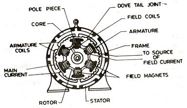
Every DC motor has six basic parts -- axle, rotor (a.k.a., armature), stator, commutator, field magnet(s), and brushes. In most common DC motors (and all that BEAMers will see), the external magnetic field is produced by high-strength permanent magnets1. The stator is the stationary part of the motor -- this includes the motor casing, as well as two or more permanent magnet pole pieces. The rotor (together with the axle and attached commutator) rotate with respect to the stator. The rotor consists of windings (generally on a core), the windings being electrically connected to the commutator. The above diagram shows a common motor layout -- with the rotor inside the stator (field) magnets.
The geometry of the brushes, commutator contacts, and rotor windings are such that when power is applied, the polarities of the energized winding and the stator magnet(s) are misaligned, and the rotor will rotate until it is almost aligned with the stator's field magnets. As the rotor reaches alignment, the brushes move to the next commutator contacts, and energize the next winding. Given our example two-pole motor, the rotation reverses the direction of current through the rotor winding, leading to a "flip" of the rotor's magnetic field, driving it to continue rotating.
In real life, though, DC motors will always have more than two poles (three is a very common number). In particular, this avoids "dead spots" in the commutator. You can imagine how with our example two-pole motor, if the rotor is exactly at the middle of its rotation (perfectly aligned with the field magnets), it will get "stuck" there. Meanwhile, with a two-pole motor, there is a moment where the commutator shorts out the power supply (i.e., both brushes touch both commutator contacts simultaneously). This would be bad for the power supply, waste energy, and damage motor components as well. Yet another disadvantage of such a simple motor is that it would exhibit a high amount of torque "ripple" (the amount of torque it could produce is cyclic with the position of the rotor).
In any electric motor, operation is based on simple electromagnetism. A current-carrying conductor generates a magnetic field; when this is then placed in an external magnetic field, it will experience a force proportional to the current in the conductor, and to the strength of the external magnetic field. As you are well aware of from playing with magnets as a kid, opposite (North and South) polarities attract, while like polarities (North and North, South and South) repel. The internal configuration of a DC motor is designed to harness the magnetic interaction between a current-carrying conductor and an external magnetic field to generate rotational motion.
Every DC motor has six basic parts -- axle, rotor (a.k.a., armature), stator, commutator, field magnet(s), and brushes. In most common DC motors (and all that BEAMers will see), the external magnetic field is produced by high-strength permanent magnets1. The stator is the stationary part of the motor -- this includes the motor casing, as well as two or more permanent magnet pole pieces. The rotor (together with the axle and attached commutator) rotate with respect to the stator. The rotor consists of windings (generally on a core), the windings being electrically connected to the commutator. The above diagram shows a common motor layout -- with the rotor inside the stator (field) magnets.
The geometry of the brushes, commutator contacts, and rotor windings are such that when power is applied, the polarities of the energized winding and the stator magnet(s) are misaligned, and the rotor will rotate until it is almost aligned with the stator's field magnets. As the rotor reaches alignment, the brushes move to the next commutator contacts, and energize the next winding. Given our example two-pole motor, the rotation reverses the direction of current through the rotor winding, leading to a "flip" of the rotor's magnetic field, driving it to continue rotating.
In real life, though, DC motors will always have more than two poles (three is a very common number). In particular, this avoids "dead spots" in the commutator. You can imagine how with our example two-pole motor, if the rotor is exactly at the middle of its rotation (perfectly aligned with the field magnets), it will get "stuck" there. Meanwhile, with a two-pole motor, there is a moment where the commutator shorts out the power supply (i.e., both brushes touch both commutator contacts simultaneously). This would be bad for the power supply, waste energy, and damage motor components as well. Yet another disadvantage of such a simple motor is that it would exhibit a high amount of torque "ripple" (the amount of torque it could produce is cyclic with the position of the rotor).
Signal (electrical engineering)
In the fields of communications, signal processing, and in electrical engineering more generally, a signal is any time-varying or spatial-varying quantity.
In the physical world, any quantity measurable through time or over space can be taken as a signal. Within a complex society, any set of human information or machine data can also be taken as a signal. Such information or machine data (for example, the dots on a screen, the ink making up text on a paper page, or the words now flowing into the reader's mind) must all be part of systems existing in the physical world – either living or non-living.
Some definitions
Signals can be categorized in various ways. The most common distinction is between discrete and continuous spaces that the functions are defined over, for example discrete and continuous time domains. Discrete-time signals are often referred to as time series in other fields. Continuous-time signals are often referred to as continuous signals even when the signal functions are not continuous; an example is a square-wave signal.
Discrete-time and continuous-time signals
If for a signal, the quantities are defined only on a discrete set of times, we call it a discrete-time signal. In other words, a discrete-time real (or complex) signal can be seen as a function from the set of integers to the set of real (or complex) numbers.
A continuous-time real (or complex) signal is any real-valued (or complex-valued) function which is defined for all time t in an interval, most commonly an infinite interval.
Analog and digital signals
Less formally than the theoretical distinctions mentioned above, two main types of signals encountered in practice are analog and digital. In short, the difference between them is that digital signals are discrete and quantized, as defined below, while analog signals possess neither property.
Examples of signals
Motion.
The motion of a particle through some space can be considered to be a signal, or can be represented by a signal. The domain of a motion signal is one-dimensional (time), and the range is generally three-dimensional. Position is thus a 3-vector signal; position and orientation is a 6-vector signal.
Sound.
Since a sound is a vibration of a medium (such as air), a sound signal associates a pressure value to every value of time and three space coordinates. A microphone converts sound pressure at some place to just a function of time, using a voltage signal as an analog of the sound signal. Compact discs (CDs). CDs contain discrete signals representing sound, recorded at 44,100 samples per second. Each sample contains data for a left and right channel, which may be considered to be a 2-vector (since CDs are recorded in stereo).
Pictures.
A picture assigns a color value to each of a set of points. Since the points lie on a plane, the domain is two-dimensional. If the picture is a physical object, such as a painting, it's a continuous signal. If the picture is a digital image, it's a discrete signal. It's often convenient to represent color as the sum of the intensities of three primary colors, so that the signal is vector-valued with dimension three.
Videos.
A video signal is a sequence of images. A point in a video is identified by its position (two-dimensional) and by the time at which it occurs, so a video signal has a three-dimensional domain. Analog video has one continuous domain dimension (across a scan line) and two discrete dimensions (frame and line).
Frequency Domain
In electronics and control systems engineering, frequency domain is a term used to describe the analysis of mathematical functions or signals with respect to frequency, rather than time.Speaking non-technically, a time-domain graph shows how a signal changes over time, whereas a frequency-domain graph shows how much of the signal lies within each given frequency band over a range of frequencies. A frequency-domain representation can also include information on the phase shift that must be applied to each sinusoid in order to be able to recombine the frequency components to recover the original time signal.A given function or signal can be converted between the time and frequency domains with a pair of mathematical operators called a transform. An example is the Fourier transform, which decomposes a function into the sum of an (potentially infinite) number of sine wave frequency components. The 'spectrum' of frequency components is the frequency domain representation of the signal. The inverse Fourier transform converts the frequency domain function back to a time function.A spectrum analyzer is the tool commonly used to visualize real-world signals in the frequency domain.
Magnitude and phase:
In using the Laplace, Z-, or Fourier transforms, the frequency spectrum is complex, describing the magnitude and phase of a signal, or of the response of a system, as a function of frequency. In many applications, phase information is not important. By discarding the phase information it is possible to simplify the information in a frequency domain representation to generate a frequency spectrum or spectral density. A spectrum analyzer is a device that displays the spectrum.
The power spectral density is a frequency-domain description that can be applied to a large class of signals that are neither periodic nor square-integrable; to have a power spectral density a signal needs only to be the output of a wide-sense stationary random process.
Different frequency domains
Although "the" frequency domain is spoken of in the singular, there are actually several different frequency domains, each defined by a different mathematical transform, which are used to analyze signals. These are the most common transforms used and the fields in which they are used:
Fourier series - repetitive signals, oscillating systems Fourier transform - nonrepetitive signals Laplace transform - electronic circuits and control systems Z transform - discrete signals, digital signal processing wavelet transform - digital image processing, signal compression.
Operation Of Dc Machine
The operation of a DC motor is dependent on the workings of the poles of the stator with a part of the rotor, or armature. The stator contains an even number of poles of alternating magnetic polarity, each pole consisting of an electromagnet formed from a pole winding wrapped around a pole core. When a DC current flows through the winding, a magnetic field is formed. The armature A cross section of a simple direct-current electric motor. At its center is the rotor, a coil wound around an iron armature, which spins within the poles of the magnet that can be seen on the inside of the casing. Photograph by Bruce Iverson. Science Photo Library, National Audubon Society Collection/Photo Researchers, Inc. Reproduced by permission. also contains a winding, in which the current flows in the direction illustrated. This armature current interacts with the magnetic field in accordance with Ampère's law, producing a torque which turns the armature.
If the armature windings were to rotate round to the next pole piece of opposite polarity, the torque would operate in the opposite direction, thus stopping the armature. In order to prevent this, the rotor contains a commutator which changes the direction of the armature current for each pole piece that the armature rotates past, thus ensuring that the windings passing, for example, a pole of north polarity will all have current flowing in the same direction, while the windings passing south poles will have oppositely flowing current to produce a torque in the same direction as that produced by the north poles. The commutator generally consists of a split contact ring against which the brushes applying the DC current ride.
The rotation of the armature windings through the stator field generates a voltage across the armature which is known as the counter EMF (electromotive force) since it opposes the applied voltage: this is the consequence of Faraday's law. The magnitude of the counter EMF is dependent on the magnetic field strength and the speed of the rotation of the armature. When the DC motor is initially turned on, there is no counter EMF and the armature starts to rotate. The counter EMF increases with the rotation. The effective voltage across the armature windings is the applied voltage minus the counter EMF.
University College of Engineering & Technology
In order to provide quality education of engineering to the people belonging to the Southern Punjab, an Engineering College was established by the directive of Ex-Prime Minister of Pakistan on the request of the Vice-Chancellor on the occasion of 1st convocation of this university held on 23rd February 1999. The University administration took the matter seriously and a devoted team of academic as well as administrative staff worked out the practical details of this project. Currently 47 faculty members are teaching and 1050 students are studying in four different specializations of Electrical Engineering (Electronics, Computer Systems, Power and Telecommunication). The college has excellent infrastructure comprising of well equipped laboratories, spacious class rooms, well stacked library and most modern computer labs. A new building of University College of Engineering & Technology equipped with latest facilities is also completed recently at a cost of Rs. 200 million. The faculty members of University College of Engineering & Technology have been constantly working to impart quality education to the students. Engineers produced by this institution are playing an affirmative role in leading the nation in the 21st century. Electronic and Computer Systems programs of this College have been accredited by Pakistan Engineering Council while the accreditation process of Power and Telecommunication programs is under way after interim visit of Pakistan Engineering Council team.
Subscribe to:
Posts (Atom)